Introduction
Nowadays, electricity power rates are going higher and higher so keeping track of your consumption is not a bad idea to undertake. In this post, I will show you how you can use your ESP32 microcontroller to retrieve AC load parameters using the PZEM-004T module using the Arduino framework. Voltage, current, power, etc for each AC load can be retrieved accurately by using this module. We will program our ESP32 to retrieve readings from multiple PZEM-004T by connecting it to a single Universal Asynchronous Receiver-Transmitter(UART) or Serial port.
If you want to see this project in video format then please see this video below or watch it on my YouTube or Facebook channel.
What is the PZEM-004T module?
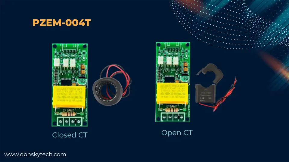
The upgraded PZEM-004T version 3 module mainly retrieves voltage, current, frequency, power factor, etc., from AC loads or devices. This allows you to know your energy readings or consumption. It comes in a Closed or Open CT coil that you will attach to your AC load live line to retrieve the necessary readings.
The PZEM-004T module contains connectors on each side. The left-hand side shows the AC load connection. The right-hand side is where serial communication with your computer or microcontroller can be attached.
You can find the complete datasheet for the PZEM-004T module at this link.
Prerequisites
You should be familiar with the PlatformIO IDE extension in Visual Studio Code before reading this post. You can read my earlier post entitled PlatformIO Tutorial for Arduino Development if you would like a step-by-step tutorial on this.
I have used PlatformIO in developing this project as it is far easier to develop Arduino programs using the different tools offered by Visual Studio Code instead of the traditional Arduino IDE.
About the MycilaPZEM004Tv3 PZEM-004T Library
The MycilaPZEM004Tv3 is written by Mathieu Carbou who have written and maintained several Arduino libraries. It is specifically written for the ESP32 microcontrollers and contains several features such as a blocking/nonblocking mode.
The library is very responsive and fast as you can see the readings without any delay. Using Visual Studio Code allows you to easily use this library on your projects.
Parts/Components Required
This project uses the following components:
- ESP32 – Amazon | AliExpress
- PZEM-004T – Amazon | AliExpress
- Breadboard – Amazon | AliExpress
- Connecting Wires – Amazon | AliExpress
Disclosure: These are affiliate links and I will earn small commissions to support my site when you buy through these links.
If you are in the Philippines or Southeast Asia, please visit and purchase from my store for your IoT needs. 🙂
Schematic/Wiring
By default, the ESP32 contains multiple Serial ports for communicating with serial devices. We are using the Hardware Serial port of our ESP32 to send messages back and forth between them using Serial Communication.
Read Next:
Pico W -MicroPython MQTT – BMP/BME 280 Weather Station
Control DS18B20 using MicroPython with a Weather Station Project
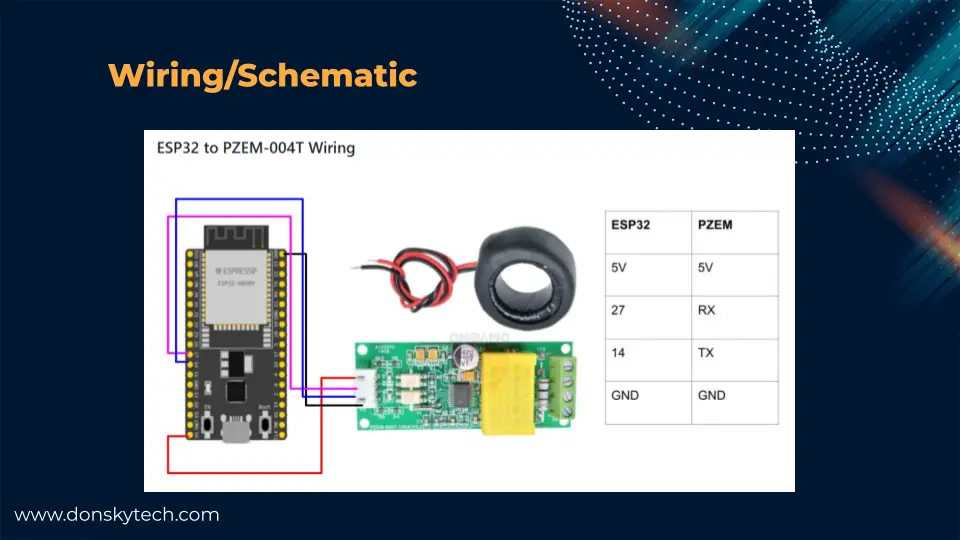
ESP32 and Single PZEM-004T connection
The following are the wiring connections between the ESP32 and the PZEM-004T module. For my NodeMCU ESP32 38 pins microcontroller board, I am using the hardware serial pins GPIO27 and GPIO14.
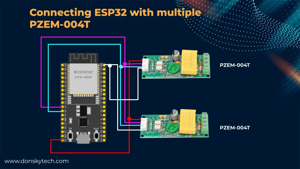
ESP32 and Multiple PZEM-004T connection
If your ESP32 needs to monitor multiple PZEM-004T, it should follow the image below. All PZEM-004T modules’ Rx and Tx pins will connect to the same HardwareSerial GPIO pins.
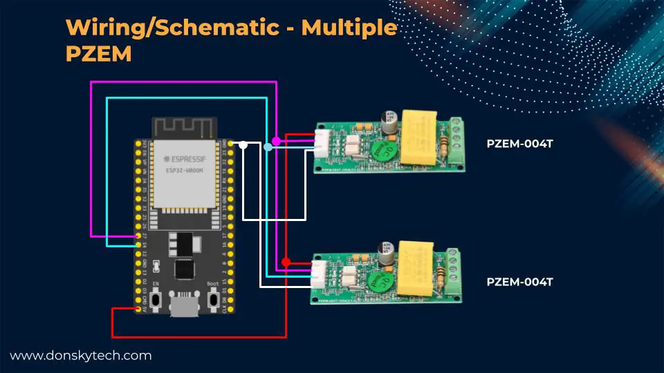
You might be asking how the ESP32 can know which PZEM-004T it is communicating with. The answer is to set a unique device ID for each PZEM-004T module. When we start communicating with each PZEM using the library, we need to pass in the unique device ID or address for each module. The code section will show you how this is done.
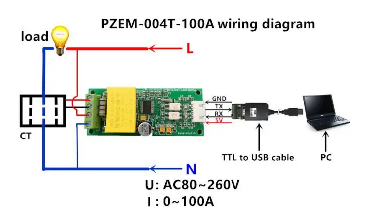
ESP32, PZEM-004T, and AC Load Wiring
The image below shows how to connect the AC Load to your PZEM-004T.
Note
Please be careful when working with AC main voltages as there is risk of electrocution
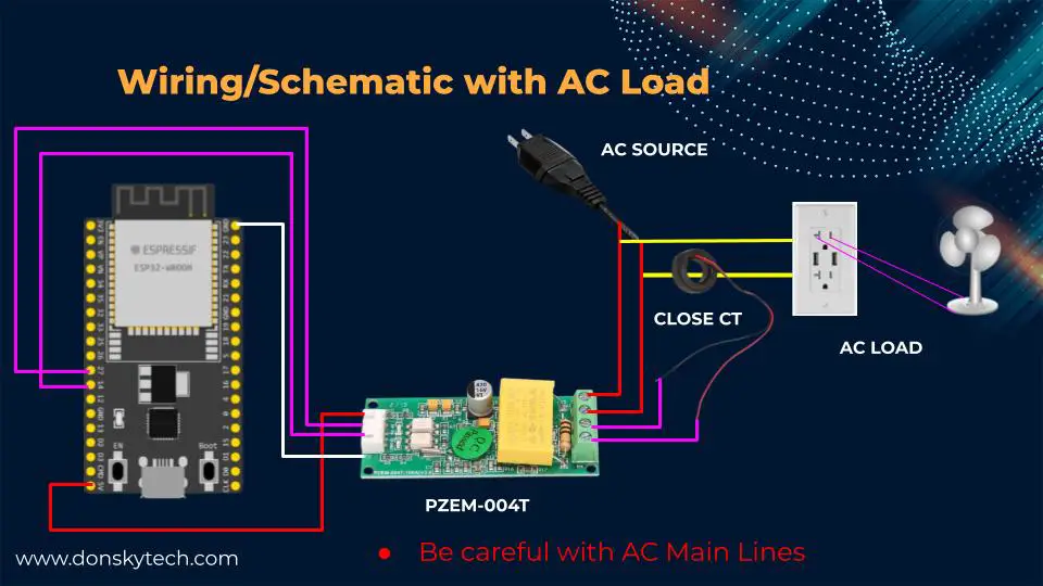
Follow the wiring and connection above when you are attaching the AC main line and the load. Ensure there is no shorting to prevent electric sparks. Use a multitester for this particular purpose.
Attach the coil of your PZEM-004T to the active line of your main line if you are using the Close CT type. Otherwise, if you are using the Open CT type then open it and attach it to the active line also.
Code
Before running the code, ensure an AC load is connected to the PZEM-004T module to energize the entire circuit.
The first thing that you need to accomplish is to set a unique device ID or address for each PZEM-004T module. This will allow the library that we will be using to know which module it is talking to.
Setting the Device ID for each PZEM-004T
Below is the code that you need to set the unique device ID for each of your PZEM-004T. This is taken directly from the SetAddress.ino file. I commented on the part that I feel is unnecessary for setting the unique device id.
We will upload this sketch for each PZEM-004T that you are going to connect to your ESP32. Assign a unique device ID to each module to avoid any mix-up in retrieving the load parameters.
/*
 * This example shows how to set an address to a PZEM004Tv3 device.
 *
 * The circuit:
 * - PZEM004Tv3 connected to Serial1 (RX=14, TX=27)
 */
#include <Arduino.h>
#include <ArduinoJson.h>
#include <MycilaPZEM004Tv3.h>

Mycila::PZEM pzem;

void setup() {
  Serial.begin(115200);
  while (!Serial)
    continue;

  JsonDocument doc;

  pzem.begin(Serial1, 14, 27);
  uint8_t address = pzem.getDeviceAddress();

  // pzem.read();
  // pzem.toJson(doc.to<JsonObject>());
  // Serial.printf("0x%02X ", pzem.getDeviceAddress());
  // serializeJson(doc, Serial);
  // Serial.println();

  // address += 100;
  // if (pzem.setDeviceAddress(address)) {
  //   Serial.printf("Address set to 0x%02X\n", pzem.getDeviceAddress());
  // }

  // pzem.read();
  // pzem.toJson(doc.to<JsonObject>());
  // Serial.printf("0x%02X ", pzem.getDeviceAddress());
  // serializeJson(doc, Serial);
  // Serial.println();

  // uint8_t finalAddress = 0x01;
  // uint8_t finalAddress = 0x02;
  uint8_t finalAddress = 0x03;
  if (pzem.setDeviceAddress(finalAddress)) {
    Serial.printf("Address set to 0x%02X\n", pzem.getDeviceAddress());
  }

  pzem.end();
}

void loop() {
  vTaskDelete(NULL);
}
Note
Make sure that an AC load is connected to your PZEM-004T prior to running this sketch
Let’s go over to each line of the program.
#include <Arduino.h>
#include <ArduinoJson.h>
#include <MycilaPZEM004Tv3.h>

Mycila::PZEM pzem;
First, we import the necessary header files that we need in order for us to communicate with our PZEM-004T. In this project, we will only need the ArduinoJson project and the MycilaPZEM004Tv3 We declare an instance of the PZEM class from the Mycila namespace.
void setup() {
  Serial.begin(115200);
  while (!Serial)
    continue;

  JsonDocument doc;

  pzem.begin(Serial1, 14, 27);
  uint8_t address = pzem.getDeviceAddress();
In the setup() function, we initialized our serial port with the necessary baud rate. We begin communicating with our PZEM-004T using the UART1 or the Serial1 object and we try to retrieve the device address of the module.
  uint8_t finalAddress = 0x03;
  if (pzem.setDeviceAddress(finalAddress)) {
    Serial.printf("Address set to 0x%02X\n", pzem.getDeviceAddress());
  }

  pzem.end();
}

void loop() {
  vTaskDelete(NULL);
}
After which, we set the unique device ID to 0x03 and then call the method pzem.setDeviceAddress(finalAddress) to finally set the address. We terminate the connection using the pzem.end() command. In the loop() function, we just delete the currently running loop() function.
After uploading the above sketch, the following messages will print to your terminal, indicating that the connected module has been assigned a unique device ID.
Address set to 0x03How to retrieve the PZEM-004T readings?
In order for us to retrieve the readings for each PZEM-004T then we can upload the following ReadMultiAsync.ino sketch to your ESP32 from the examples folder of the library.
/*
  * This example shows how to read the energy data of several PZEM004Tv3 devices on the same Serial port.
  * PZEM have to be assigned addresses before using this example.
  *
  * The circuit:
  * - PZEM004Tv3 #1 connected to Serial1 (RX=14, TX=27)
  * - PZEM004Tv3 #2 connected to Serial1 (RX=14, TX=27)
  *
  * Compile with -D MYCILA_JSON_SUPPORT to enable JSON support
  * Add ArduinoJson library to your project
*/
#include <Arduino.h>
#include <ArduinoJson.h>
#include <MycilaPZEM004Tv3.h>

Mycila::PZEM pzem1; // 0x01
Mycila::PZEM pzem2; // 0x02

void setup() {
  Serial.begin(115200);
  while (!Serial)
    continue;

  pzem1.begin(Serial1, 14, 27, 0x01, true);
  pzem2.begin(Serial1, 14, 27, 0x02, true);
}

void loop() {
  delay(1000);
  if (pzem1.isEnabled()) {
    JsonDocument doc;
    pzem1.toJson(doc.to<JsonObject>());
    Serial.printf("0x%02X ", pzem1.getDeviceAddress());
    serializeJson(doc, Serial);
    Serial.println();
  }

  if (pzem2.isEnabled()) {
    JsonDocument doc;
    pzem2.toJson(doc.to<JsonObject>());
    Serial.printf("0x%02X ", pzem2.getDeviceAddress());
    serializeJson(doc, Serial);
    Serial.println();
  }
}
Let us analyze what each line does.
#include <Arduino.h>
#include <ArduinoJson.h>
#include <MycilaPZEM004Tv3.h>

Mycila::PZEM pzem1; // 0x01
Mycila::PZEM pzem2; // 0x02
Again, we import the necessary libraries to communicate with our PZEM-004T module and declare two instances of the PZEM class from the Mycila namespace.
void setup() {
  Serial.begin(115200);
  while (!Serial)
    continue;

  pzem1.begin(Serial1, 14, 27, 0x01, true);
  pzem2.begin(Serial1, 14, 27, 0x02, true);
}
In this section, we initialize our Serial monitor and begin communicating with our PZEM-004T module passing in the device ID and the asynchronous flag.
void loop() {
  delay(1000);
  if (pzem1.isEnabled()) {
    JsonDocument doc;
    pzem1.toJson(doc.to<JsonObject>());
    Serial.printf("0x%02X ", pzem1.getDeviceAddress());
    serializeJson(doc, Serial);
    Serial.println();
  }

  if (pzem2.isEnabled()) {
    JsonDocument doc;
    pzem2.toJson(doc.to<JsonObject>());
    Serial.printf("0x%02X ", pzem2.getDeviceAddress());
    serializeJson(doc, Serial);
    Serial.println();
  }
To check for the PZEM reading, we check if the module is enabled and retrieve the readings by calling the toJson() method of each PZEM object. We then print the output to our serial monitor.
You can loop to each of the PZEM-004T modules attached to your ESP32 microcontroller so that you can retrieve the readings. The sample output of the readings from our PZEM-004T module is shown below.
0x01 {"enabled":true,"address":1,"time":16591,"frequency":60.2,"voltage":238.3,"current":0.025,"active_power":2.9,"reactive_power":5.159173,"apparent_power":5.918367,"power_factor":0.49,"active_energy":0.02,"resistance":4640,"dimmed_voltage":116,"nominal_power":12.23855,"thdi":1.779025}
0x02 {"enabled":true,"address":3,"time":16648,"frequency":60.2,"voltage":238,"current":0.234,"active_power":55.4,"reactive_power":7.894073,"apparent_power":55.9596,"power_factor":0.99,"active_energy":0.189,"resistance":1011.761,"dimmed_voltage":236.7522,"nominal_power":55.98554,"thdi":0.142492}
Looking at the output then you would notice relevant AC parameters such as voltage, current, frequency, etc which you can use to monitor your energy consumption.
Wrap up
Monitoring your energy consumption in your household is such an easy task using your ESP32 microcontroller and PZEM-004T modules. I have shown you in this project how easy it is to retrieve energy-related readings which you can process to determine your consumption so that you can manage your electricity cost.
If you would like to expand this project then you can pass the readings to IoT platforms such as Arduino Cloud or Blynk so that you can see it in graphical format or see it in real-time.
Read Next:
Pico W -MicroPython MQTT – BMP/BME 280 Weather Station
Control DS18B20 using MicroPython with a Weather Station Project
Leave a Reply